FUSELAGE CONSTRUCTION - Page 32.
December 14, 2003: Several road trips later
for the company, the intrepid RV builder gets another turn at making progress on the
airframe. The RIGHT armrest was riveted in during a very short session on December
6th. Since it is the mirror image of the LEFT armrest, I did not bother with any
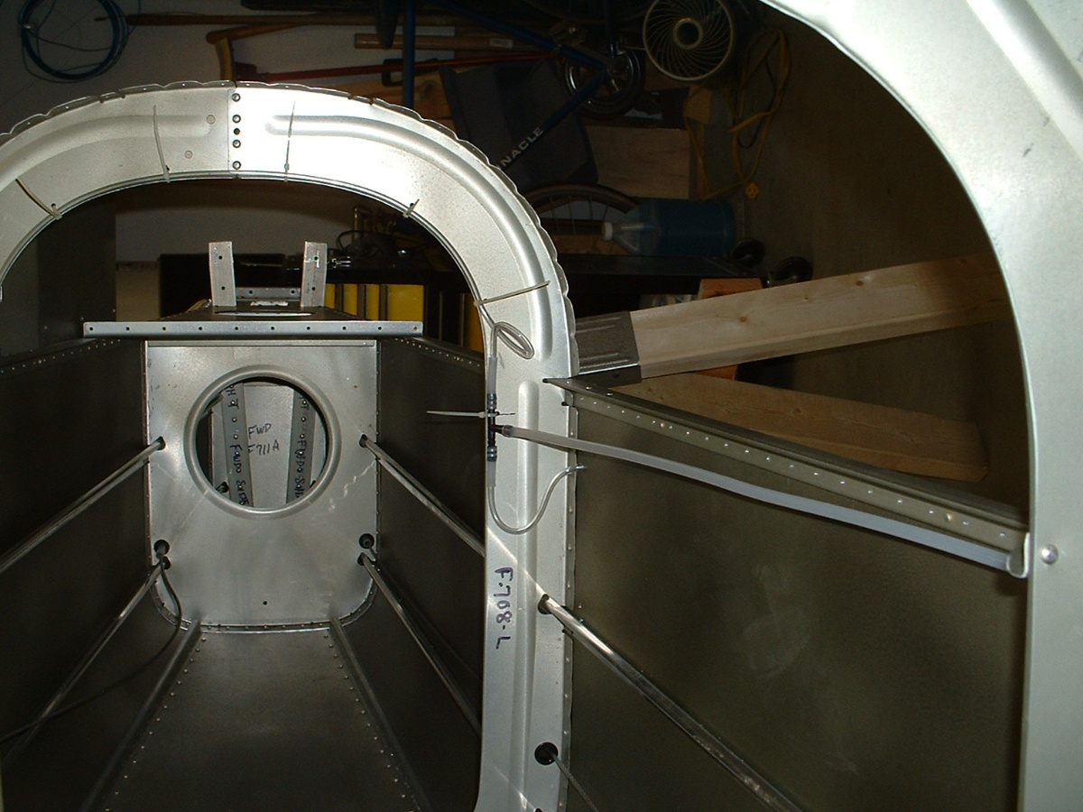
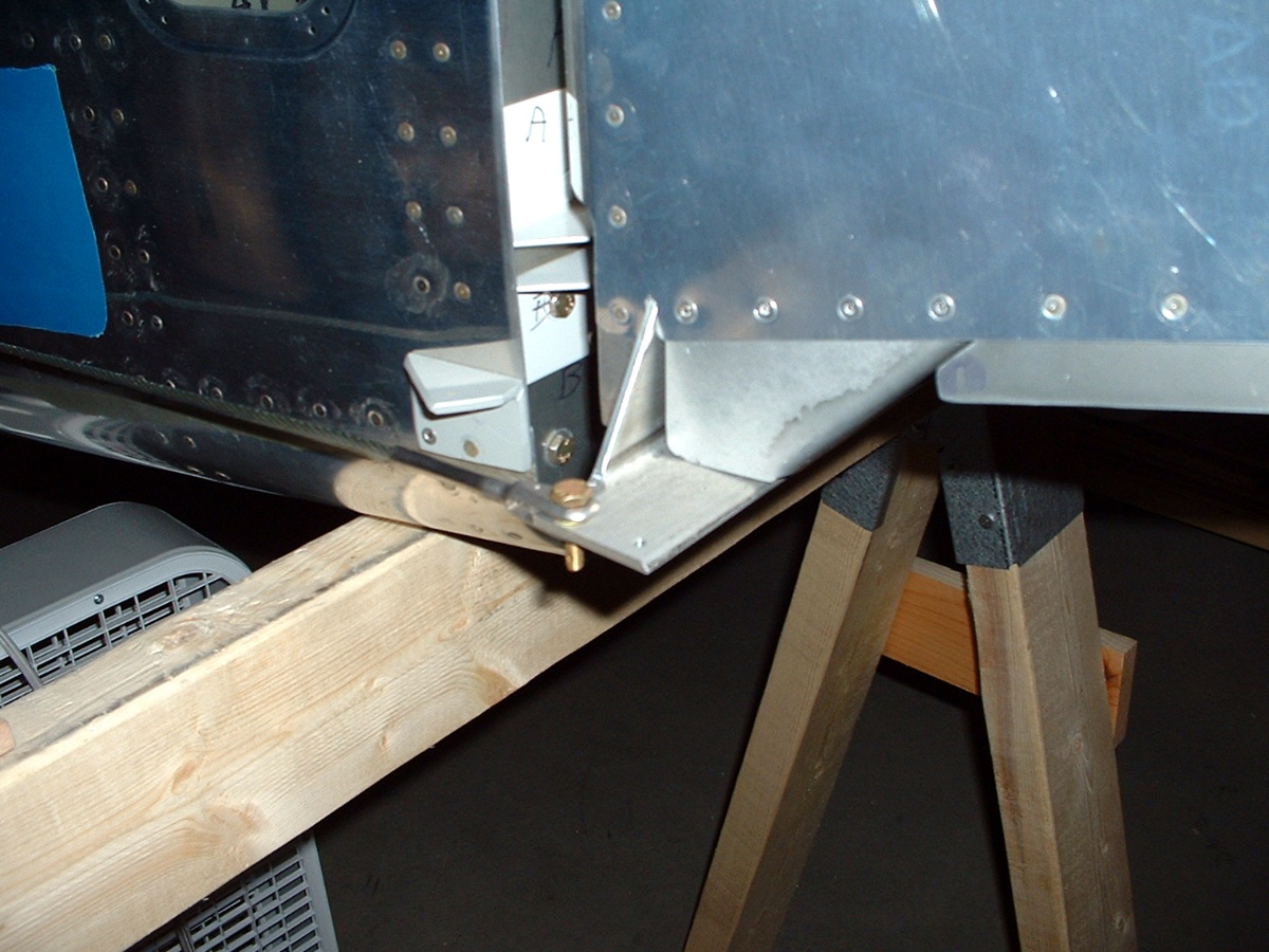
photos. Yesterday, I managed to get the static air ports installed in the aft
fuselage sides and to install the aileron manual control knob mounting plate. The
fuselage is on its LEFT side on the saw horses. I turned the camera to align with
it. As you can see at the LEFT side of this photo, gravity is pulling down the right
rudder cable since it is attached to nothing at either end. This photo was only
intended to show the static vent tubing mounted to the F-708 bulkhead.
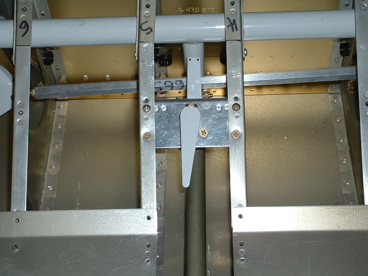
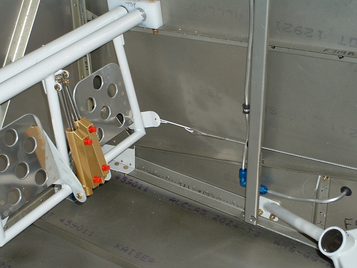
Here is the reason I had the fuselage on its side. It is much easier to
install the aileron trim control with this orientation. Again, I have aligned the
camera to a "normal" view for this part. The springs are not attached yet,
but the mechanism is in place. You can see the engraved serial number on the aft
wing-mount bulkhead just beyond the control stick assembly. That is the elevator
push-rod just below the trim control.
December 15, 2003: I installed the brake
lines, fuel tank vent lines, the fuel selector valve, and the fuel line to connect the
fuel selector valve to the LEFT fuel tank. The two pictures below show those items,
but since it was taken on the 17th, it also shows the additional work done on that day.
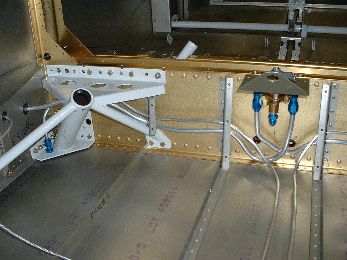
December 16, 2003: I ordered the electric fuel pump from Van's to allow me to install the fuel line from the selector valve to the pump. It will be mounted on the firewall in the picture above.
December 17, 2003: The Wright
Day to have a milestone in the RV-9A project. This
is the 100-year anniversary of the Wright Brothers first powered flight.
I finished the fuel vent ports
by installing wire mesh screens on them after grinding a 45-degree face on both ports.
I used ProSeal to attach the mesh screens to the ports. I also installed the
fuel line that runs from the fuel selector valve to the RIGHT fuel tank -- it shows up in
the second photo above this paragraph. I also installed both metal brake lines that
run from the firewall to the landing gear mounts. They are visible in both the
photos above. I will cut them to the proper length when I install the last fuel line
to the fuel pump. Here is the milestone I was talking about, the RUDDER cables are
finally attached to the RUDDER and the pedals.
Yeah, that's a temporary hookup using coat hanger wire, but I thought it would
be better to wait until tomorrow to do the real steel links when I am rested. It was
getting late when I was doing this.
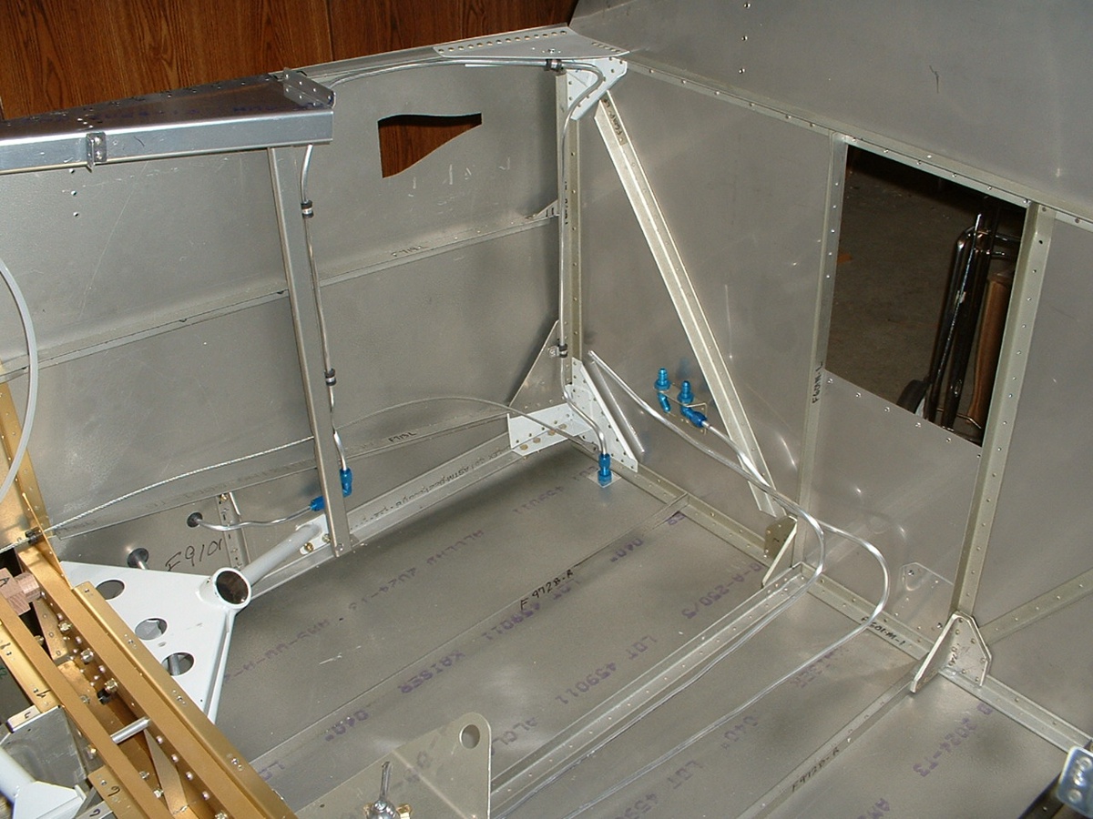
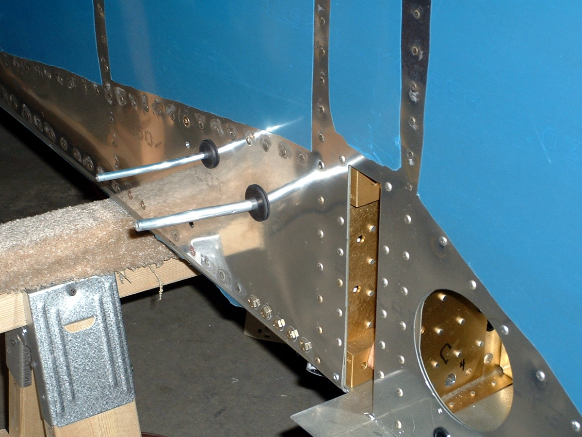
Speaking of fuel lines and vent lines running to the wing tanks, here is the
view of the lines exiting on the LEFT side of the fuselage. They will remain this
way until I get the wings attached for their initial fit, etc.
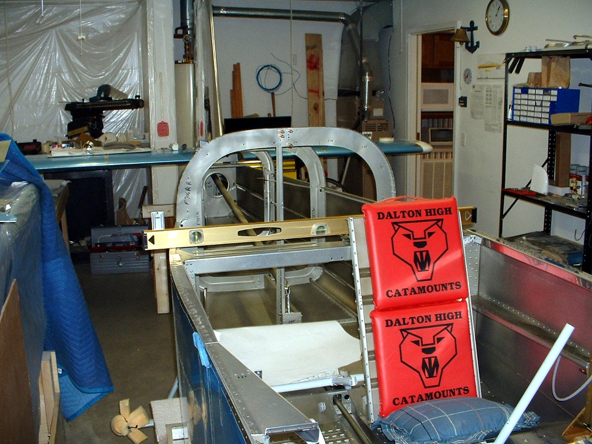
And the last shot for this page, the ceremonial photo showing the tail sections
attached again, and of course, my temporary seating arrangements to check out the rudder
pedal movement and adjustments that may be needed. The vertical stabilizer has the
blue plastic removed, making it a bit harder to see. The red cushions are from my
old high school in Dalton, Georgia (23 miles south of my current abode). Notice the
time on the clock on the wall is 1:05 AM. It is now approaching 2 AM as I get ready
to publish this updated page.
| CLICK HERE for page 33. | RETURN to MAIN MENU |