Airport Assembly - Page 123.
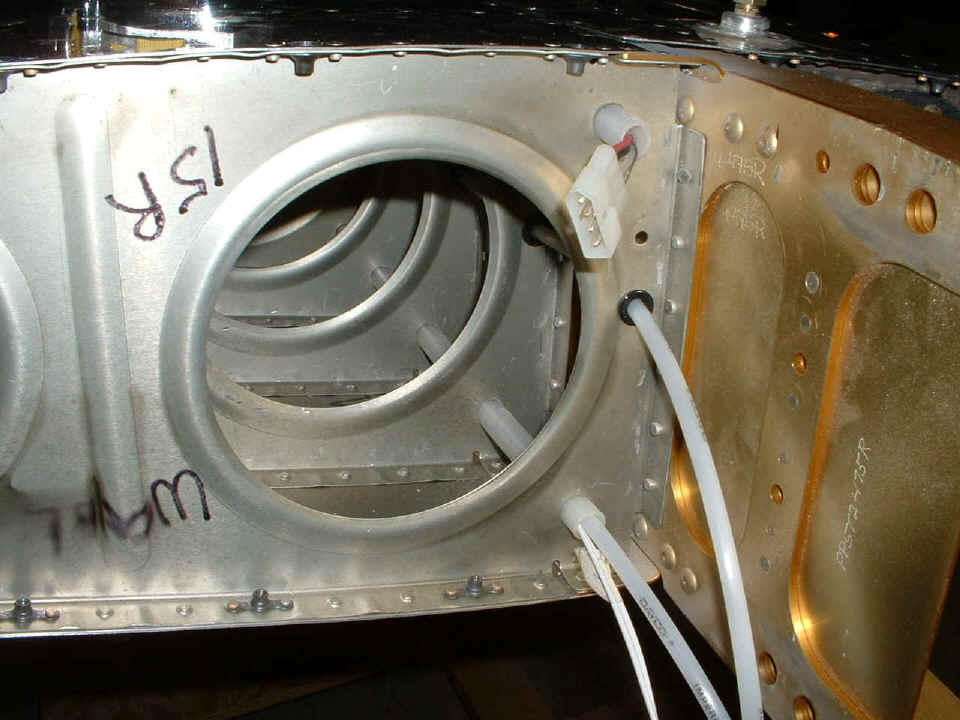
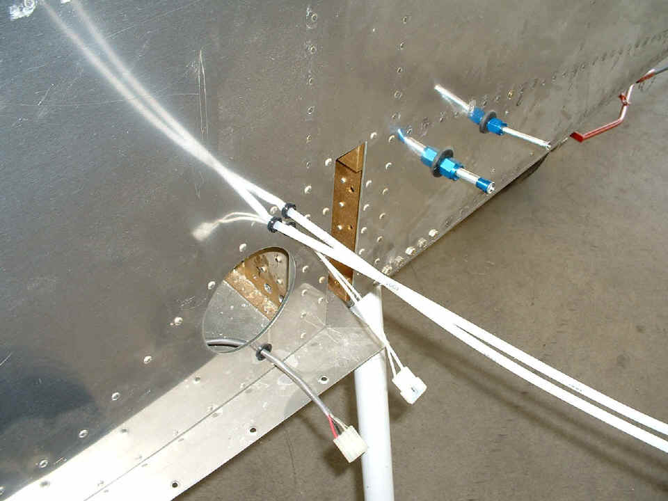
May 5, 2005: The wing root rib photo shows a
number of things. The bottom of the wing is at the top of the photo. The
strobe light wiring at the top of this photo is running through one conduit by itself with
no other wires to minimize the possibility of induced radio noise into the low-voltage
wiring. I put in one of the plastic tubes to the stall warning device with the
low-voltage wires running to the landing light and the wing-tip marker light. The
other plastic tube runs through the pitot tube holes in the ribs and the plastic bushings
all the way out to the last inspection port where the aileron bellcrank is located.
That puts the device outside the propeller arc for a clean air flow.
Remember this is the bottom side of the wing turned up on the work table.
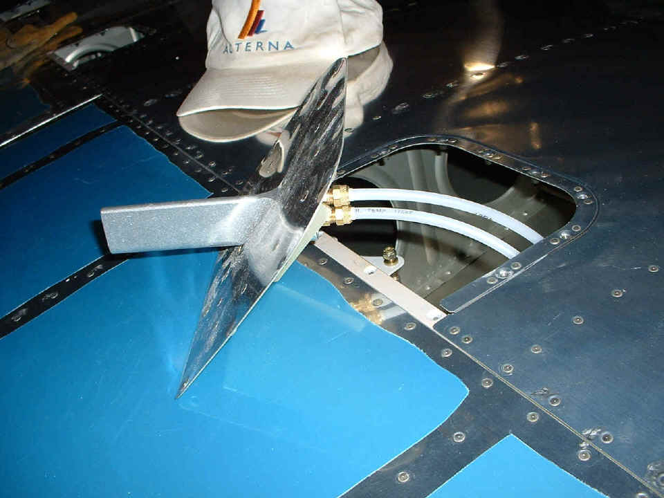
I have both tubes just stuck in the air fittings to show how the stall warning
probe is mounted on the inspection plate. I will be adjusting the angle of the
probe during flight testing to be sure the panel-mounted gauge shows the needle at the
red/white arc conjunction when the airplane is at stall speed. The initial testing
angle of the probe will be set at 50 degrees.
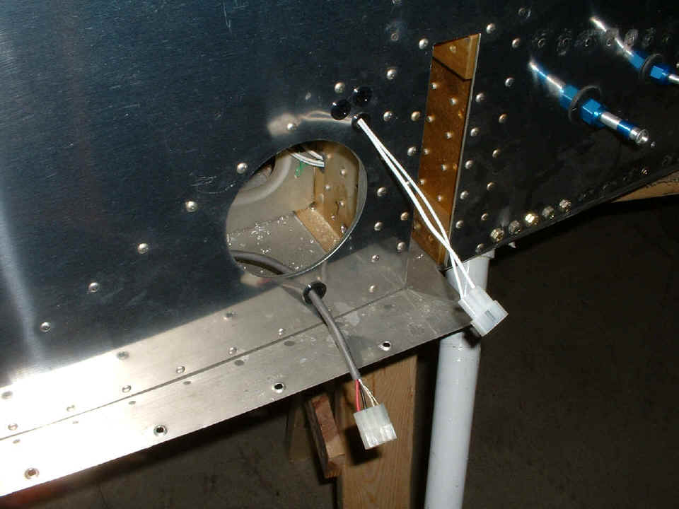
The two tubes from the probe will enter the fuselage through the new plastic
bushings I have installed near the low-voltage wires for the wing lights. The gray
cable is the high-voltage wire for the wing strobe light. Four of the dimpled screw
holes in the fuselage center bottom skin are visible at the bottom of the photo below. Number eight screws will go through these holes into the platenuts seen in the wing
root rib shown two photos above.
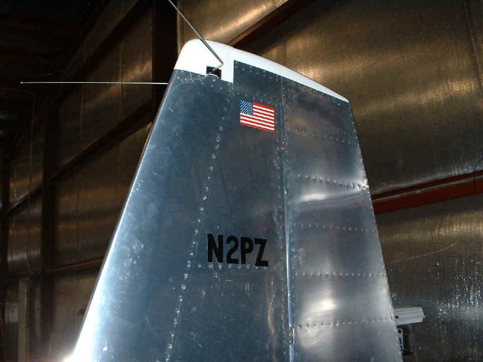
Since I missed the photo last night of the finished fiberglass cap at the top
of the vertical stabilizer, I thought I would do it justice tonight and show the colors at
the same time. The cap is secured with three 6-32 flat-head screws on each side.
The fourth screw up there is holding an aluminum filler plate that minimizes air
flow trying to get in around the "hockey puck" that holds the VOR/Glide Slope
dipole antenna in position.
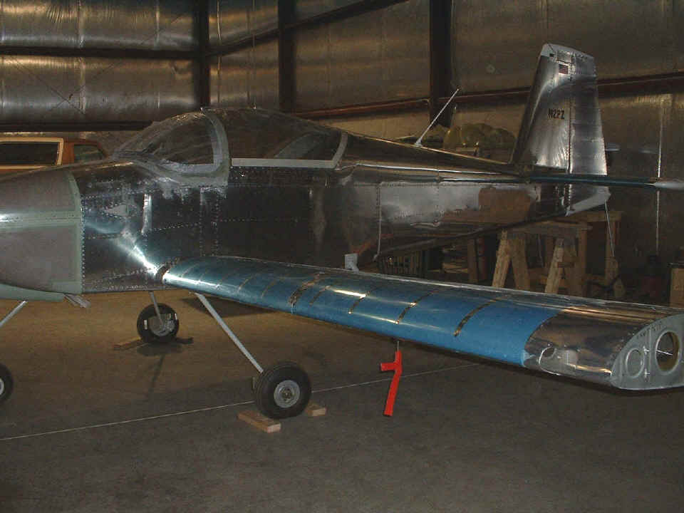
The last photo tonight puts things in perspective on the LEFT wing that was
installed yesterday. From the end of the wing spar to the fuselage it is 129 inches
where the wing spar goes into the wing spar bulkheads. The wing span will get longer
when the fiberglass wing tip is put on the end of the wing and the lights are plugged in
at last! I still have to put a ground lug on each of the landing lights and secure
them to the wing spar. I also have to put the plugs on the end of the wires hanging
out of the wings.
It was 10 PM when I stopped work on the airplane after a 4.5-hour session. I made it home around 10:30 PM. Midnight is fast approaching, so that is a wrap for tonight. It may be Saturday before I get back to the airport, but it will be a good day with our local EAA Chapter 150 meeting and outdoor barbecue in the afternoon. The forecast is for a sunny day and 80 degrees. I should have the RIGHT wing mounted before the meeting begins. I will take some pictures at the barbecue and post them here as well.
May 7, 2005: Saturday at
the airport all day and into the night. I worked two sessions in the hangar today
and tonight after the EAA Chapter 150 barbecue "meeting". Here are the
three pictures about the airplane work. I will put a link to the EAA pictures at the
bottom of this page. Near the top of this page you saw the preparations of the right
wing on Thursday night. This morning was the time to put the wing into the fuselage.
That started with the two new stall warning air lines going into the fuselage as I
lined up the wing on the work table.
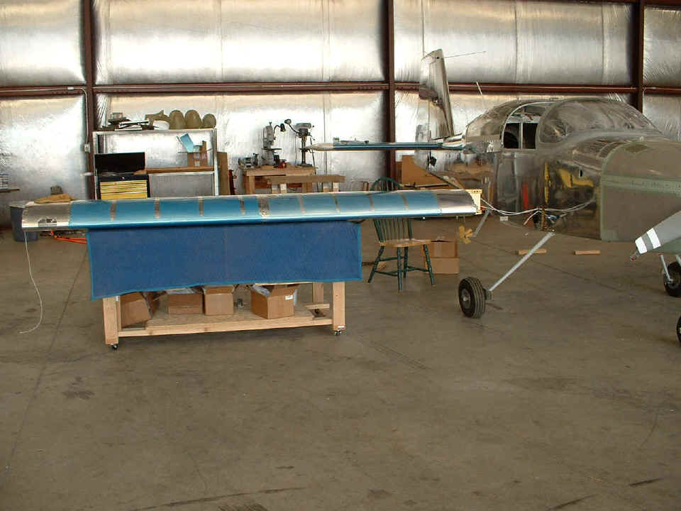
Here is the view from the front before putting the wing in position. I
was actually able to push the wing in between the wing bulkheads and insert the ACE bolts,
then the close-tolerance bolts without jacking up the airplane off the RIGHT wheel.
I wanted to try it, and it worked. Since we have seen bolts down in the spar area, I
decided not to post a photo about that again.
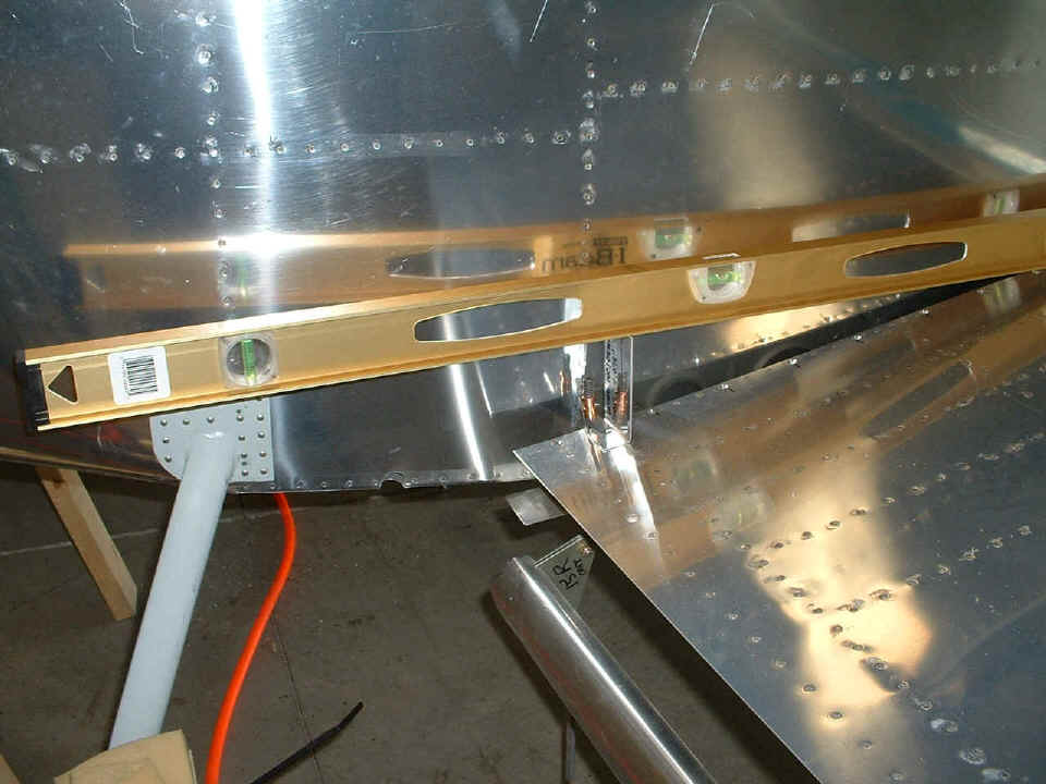
Here is something that is new, but did not get completed before the day ran out
on me. There is my wing incidence jig clamped directly above the rear spar of the
wing. What you don't see in this photo is the other short level I have up on the
canopy slide rail above the longeron to verify the airplane is level from nose to tail.
This long level is sitting on the main wing spar and the wing incidence jig and is
showing everything is fine. I realized I had not trimmed off a small amount of the
tab sticking out from the seat back bulkhead. I used my Dremel tool to make the
adjustment to the end of the tab. I did not drill the hole yet, since I also have to
confirm the wing sweep is 90-degrees to the fuselage center line. Although the flaps
are just hanging down from their bolts, I did put on the hex rod links and opened up the
holes in the bottom corner of the fuselage to allow the flaps full clearance in the UP
POSITION. Look in the photo below and you will see the cutout after it was created
using my large Unibit, then finished off with the Dremel sanding drum. If you don't
see it now, I should have a picture posted tomorrow night with the linkage connected to
mark the exact location for you.
The other things not photographed today or tonight: I repaired the "hangar rash" done to the flaps during the move to the airport. I cleaned up the strings on the floor put there to check the wing sweep. I pumped up the nose wheel tire and moved the airplane back to its storage location for the night, just in case anyone comes to the airport before I get there on Sunday morning.
Here is the link I promised to the EAA 150 barbecue held today. (Edited June 12, 2010) I received an email today from the current EAA 150 Chapter President to remove the index page for the chapter from my server as they will be putting up their own web site soon. I have retained the web page about the barbecue when I was assembling my airplane at the airport in May 2005.
| CLICK HERE for Airport Assembly - Page 124. | RETURN to MAIN MENU. |