ADS-B Out for Enterprise · · PAGE 450.
May 29, 2019: The Garmin GDL-82 ADS-B OUT transmitter arrived yesterday. I placed the order with Aircraft Spruce on May 5th when they did not have the unit in stock. The order confirmation said they would ship on May 22, 2019 and they did. I have some family occasions this weekend and will not get a chance to work on the airplane until the weekend of June 8, 2019. That is the date in 2005 when my airplane was given it's airworthiness certification on PAGE 135 of this web site. I have been reviewing a number of my older web pages today and showing them to my domestic partner Linda. She has seen my airplane at the Rockledge airport. She had a chance to see how it came together from a pile of parts to be an airplane.
I was reviewing the area under the seats to see how I could mount the Garmin GDL-82 near the radar antenna on the underside of the cabin. I confirmed the GTX-327 transponder draws less than 2 amperes and the GDL 82 uses 0.5 amperes for a total of 2.5 amps on a 5-amp circuit breaker on my panel. I have to run a power wire from that circuit breaker to the location of the GDL-82. Having a ground wire run in the same conduit allows me to pull the GDL-82 out from behind the panel for testing in the future as needed. A new short coax cable will connect the GTX-327 to the RF input to the GDL-82 and the existing cable that connects to my radar antenna will now connect to the RF output of the GDL-82. The GDL 82 has a certified GPS inside that will need to have its coaxial cable and GPS antenna mounted, probably on top of my instrument panel next to my existing GPS antenna connected to my Garmin GPS 296 I use for navigation and to control my autopilot headings. The GDL-82 size is less that 3.4 inches wide, less than 8 inches in length, and less than 1.5 inches thick. I hope to have time for a quick stop at the airport this coming Sunday to lift off the seat cushions and the "carpet" under those cushions to reveal the actual spacing between the seat ribs.
June 2, 2019: I stopped by the airport today long enough to open the canopy and put the passenger seat cushions in the baggage area, then raised the "carpet" to reveal the seat panel and screws that hold that panel to the seat ribs. The radar antenna is mounted in the space between the ribs that are between the elevator push rod center section and the right side control stick area. That section has more than adequate width for mounting the GDL-82 as it must be in the RF signal path from the GTX-327 transponder and the antenna located under this area of the cabin.
June 4, 2019: I found an amplified GPS antenna on ebay this morning with 28 dB of gain and a TNC right-angle connector on the coax cable that is 16 feet long. This antenna will also be installed on my dashboard under the windshield. The cable has plenty of length to reach the GPS receiver input connector of the GDL-82 down under the right seat. This has to be best $10 I have spent in a long time.
June 9, 2019: This was a rainy Sunday good
for working INSIDE the hangar on my airplane. The first order of business
is to remove the right side of my instrument panel to measure the available
space and clearance to install the Garmin GDL-82 ADS-B output transmitter.
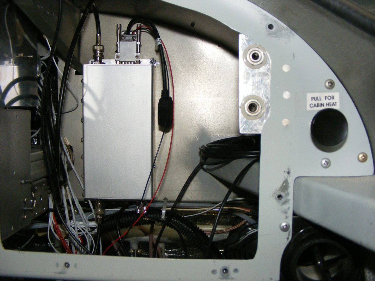
And of course, it is possible to mount the GDL-82 back there as seen here
in this temporary installation. I had a BNC to BNC 50-ohm cable which was
long enough to connect from the GTX-327 transponder output to the input
connector at the TOP left corner of the GDL-82. That DB-15 connector at
that end has the large black USB serial cable connection to program the unit and
do computer diagnostics of the unit during the installation. The RED and
BLACK wires from that connector power the unit. The BNC connector and
cable at the bottom left of the unit goes to the RADAR antenna on the bottom of
the cabin area. There is a TNC connector behind the power wires at the
bottom right corner of the unit. That cable goes to a new GPS antenna on
top of the panel. I have to rework the GDL-82 mounting screws to improve the thermal
conductivity to the bulkhead. I have to decide where I am going to
secure the excess cable from the transponder to the input of the GDL and also
the GPS antenna cable laying on the right of the unit. The power cables
need to be placed in tubing to get down to the big flexible corrugated cable
conduit that leads to the circuit breaker for the radar transponder. I
have some larger stiff cables I can use as a fish tape to get the RED and BLACK
small wires through that bundle inside the corrugated conduit.
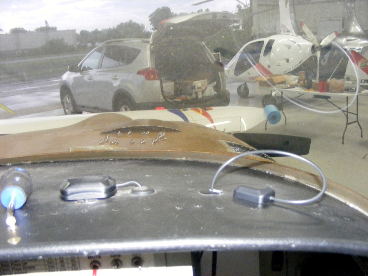
Here is the view of my existing GPS antenna for the GPS-296 and the new
antenna sitting up there next to a hole I put there in the original construction
of the airplane. The original GPS antenna is sitting on a black steel
strip I secured with pop rivets to the aluminum skin above the instrument
panel. I have measured an similar steel strip for the new antenna.
Space is limited in the area seen in the photo above. I will bring in my
smaller air drill to add the holes for the pop rivets from the inside upwards
remaining clear of the windshield. Those two pop rivets will be installed
from below as the pop rivet tool is too big and could not do it from above due
to windshield proximity. I had to remove my outside access panel to get my
bearings on all the cables back there. I have to put labels on the cables
with some masking tape for future reference.
If you go back to my PAGE 105 via THIS LINK, you can see a couple of photos of how I made that steel strip that is pop-riveted to the top skin above the instrument panel. The GPS antenna has two magnets in the base to hold the antenna in place. I used the same flat black spray paint for the steel strip and the pop-rivet heads. This was done before I put in the wind shield. This time I have to drill from the bottom up as there is no room to put in those holes from the top. The new steel strap will be my guide to put the holes in the correct location for the new GPS antenna. More pix of that installation after I do the work next weekend.
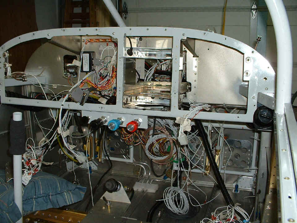
This photo is on my PAGE 87 and shows the large corrugated conduit that
feeds wires to the circuit breakers on the right side below the instrument panel
frame. I have to pull the red and black wires from the GDL-82 power plug
through this conduit to connect to the same circuit breaker that powers the
GTX-327 transponder.
June 15, 2019: I came back to work on
the airplane this Saturday. The first order of business was to remove the
temporary mounting screws and nuts from the GDL-82. I went by Ace Hardware
near my home before coming to the airport. I bought a long 1/8" drill
bit to drill the FOURTH mounting hole in the bulkhead where GDL-82 will be
permanently mounted. The changes of the hardware will improve the thermal
conductivity of the unit to the bulkhead. This was slow work as the #6
hardware had to be put in by hand using a nut driver with the nylok nut in front
of a standard 6-32 nut in the nut driver. The nylok nut kept falling out
just before I could get it started on the screw coming from the other side of
the bulkhead.
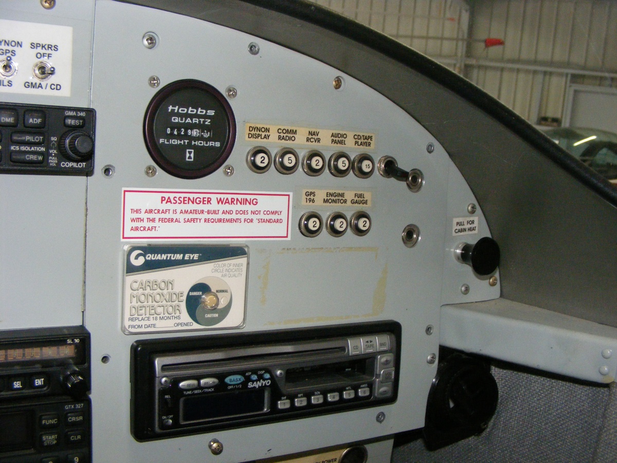
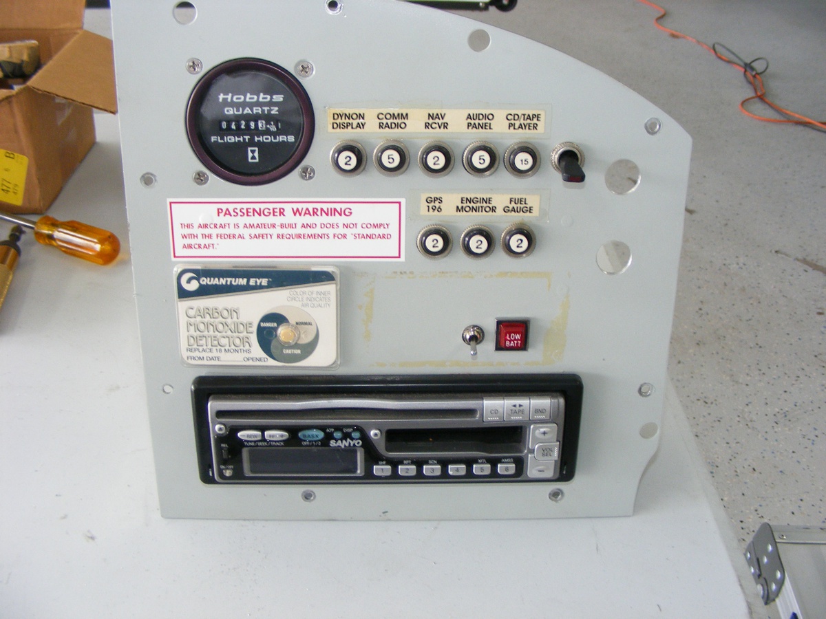
The other stops I made before heading to the airport were to get a miniature bat-handle switch and a panel-mount 12-volt LED I found at an electronics surplus warehouse on US 1 just a few miles from the house. The switch will be connected to the GDL-82 to provide anonymous ADS-B output transmissions when I squawk 1200 (VFR) from my GTX-327 radar transponder. Any other squawk code from the GTX-327 will enable the full data stream from the GDL-82.
June 16, 2019: Sunday was an easy and
short day for me, just one hour in the hangar to install the switch and LED
indicator lamp in the only free space on my right sub-panel above the car stereo
CD/Tape player combo unit. The LED indicator has the letters LOW BATT on
it, but that should be easily removed. Garmin had suggested a yellow
indicator LED for this application. It will light up if there is a fault
with the GDL-82. The switch activates the anonymous feature when 1200 is
my transponder code. I have to clean off that old adhesive in that area
before I put on new labels for these two new features. I also need to
replace the label showing GPS 196 with one that shows GPS 296. I guess it
is time to replace the top row of labels as the toggle switch is the inline
power connection to the CD/TAPE PLAYER. Before I put that switch in the
circuit, the clock in the PLAYER was slowly draining the main battery.
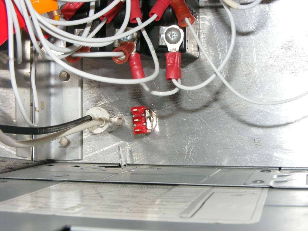
Here is the view behind that panel seen above. The LED indicator
needed a 1/2 inch round mounting hole, while the switch mounts through a
1/4-inch hole. I will remove the switch when I solder on the wires.
The BLACK wire from the LED will go to a 12-volt source, and the white wire goes
to pin 10 on the GDL-82 DB15 connector. The switch will go to pin 5 for
anonymous mode when grounding pin 5.
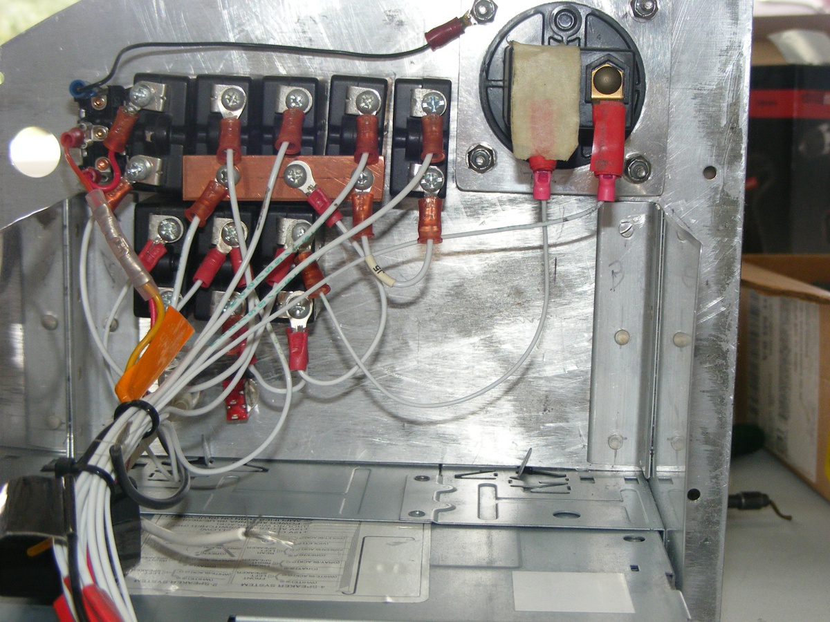
Here is the back side of the panel. The copper bus bar provides
power to the communications and navigation radios, plus the intercom. The
circuit breaker on the right near the Hobbs meter powers the Dynon D-10A.
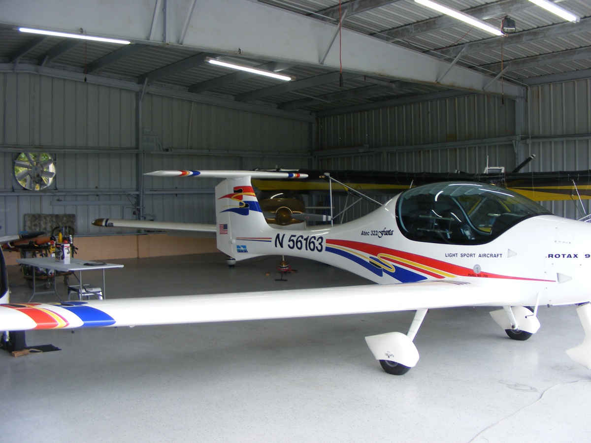
My airplane sits in the back corner for now until I need to get it out on
the ramp to test the GPS receiver inside the GDL-82 and all the other
connections. I ordered 20 feet of RED wire and 20 feed of BLACK wire, both
of which are 24 gauge for completing the wiring of the GDL to the switch, panel
mount LED, and power. Next weekend for that work.
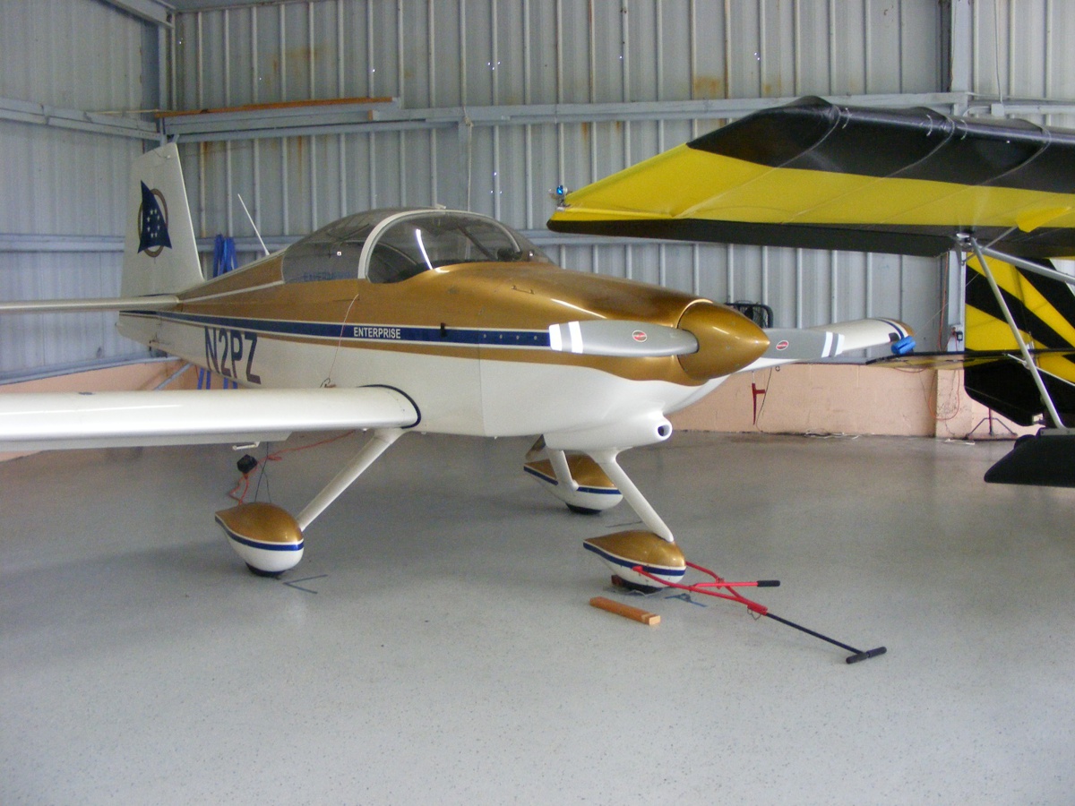
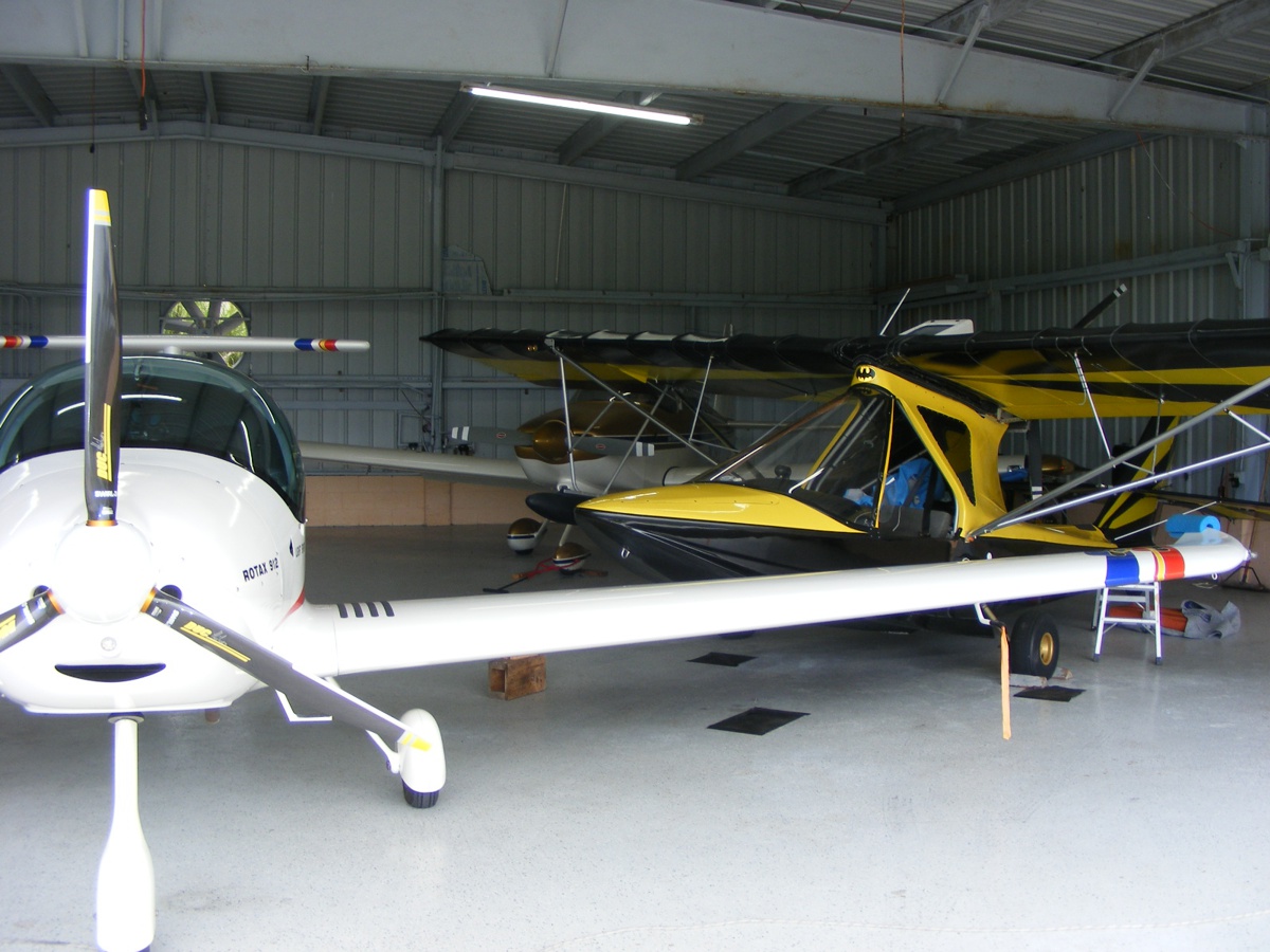
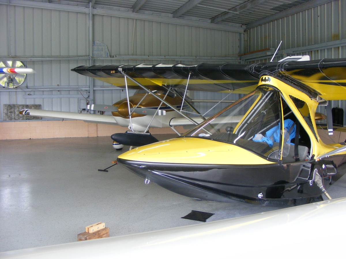
Here is a look at the other planes in the hangar.
G
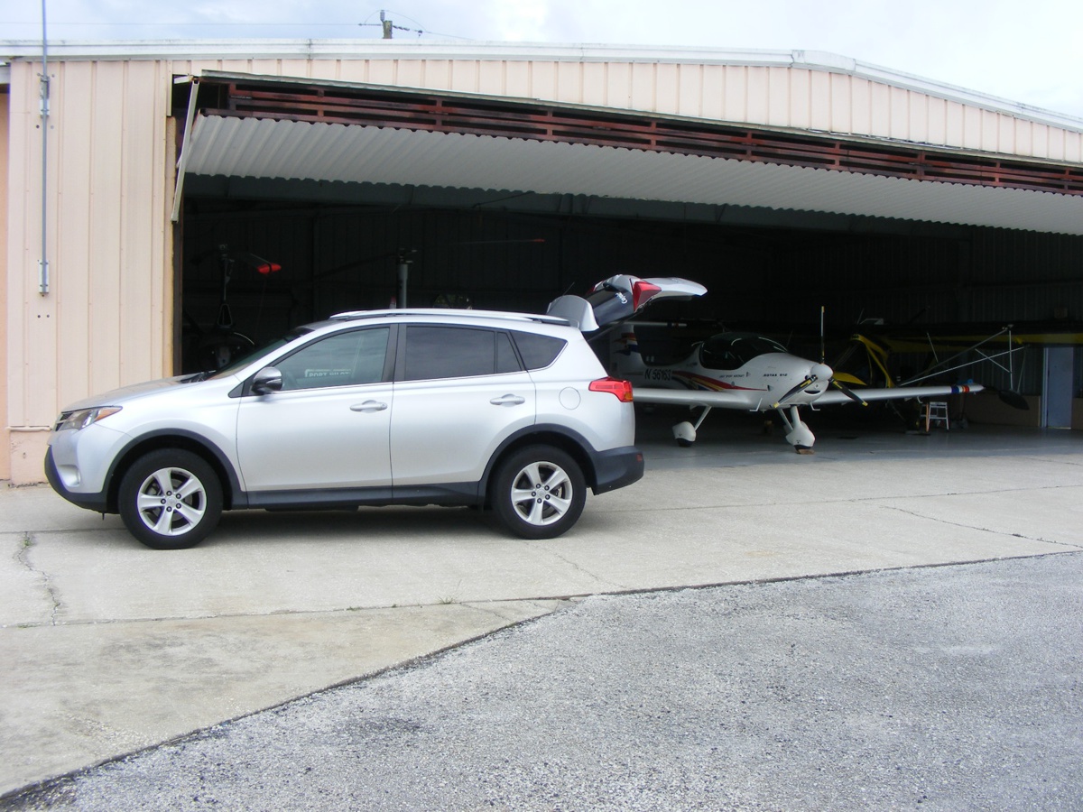
My old Caddy has a major coolant leak at the heater core. The
Toyota is going everywhere with me for now.
| CLICK HERE for PAGE 451 | Return to MAIN MENU |